
Optical Module

10Gbps 300m Duplex LC SFP+ Transceiver
description2
Maximum Supported Distances
Fiber Type |
Minimum modal bandwidth@850nm |
Min. |
Typical |
Max. |
Unit |
62.5µm MMF |
160MHz*km |
2 |
|
26 |
m |
OM1:200MHz*km |
2 |
|
33 |
m |
|
|
50µm MMF |
400MHz*km |
2 |
|
66 |
m |
OM2:500MHz*km |
2 |
|
82 |
m |
|
OM3:2000MHz*km |
2 |
|
300 |
m |
|
OM4:4700MHz*km |
2 |
|
400 |
m |
Specification parameter
Name |
10G multimode |
||
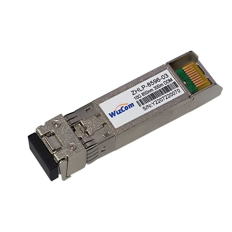
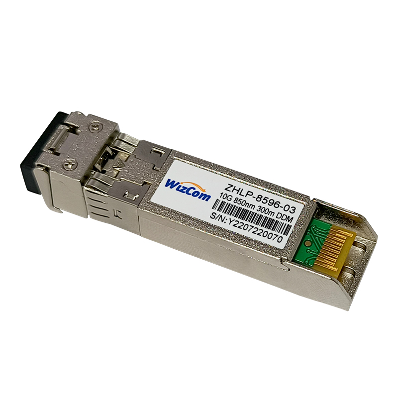
Model number |
ZHLP-8596-03 |
Brand |
Zhilian Hengtong |
Package type |
SFP+ |
Transmission rate |
10G |
Wave length |
850nm |
Transmission distance |
300m |
Port |
LC |
Fiber type |
50/125µm MMF(OM3) |
Laser type |
VCSEL |
Receiver type |
PIN |
Transmitted optical power |
-7~-1dBm |
Receiving sensitivity |
-11.1dbm |
Power |
<0.99W |
Receive overload |
-1dBm |
Power dissipation |
|
Extinction ratio |
≥3.5DB |
CDR (Clock Data Recovery) |
|
FEC function |
|
Commercial temperature |
0~70℃ |
Agreement |
SFP+ MSA/ SFF-8472/ IEEE802.3ae |
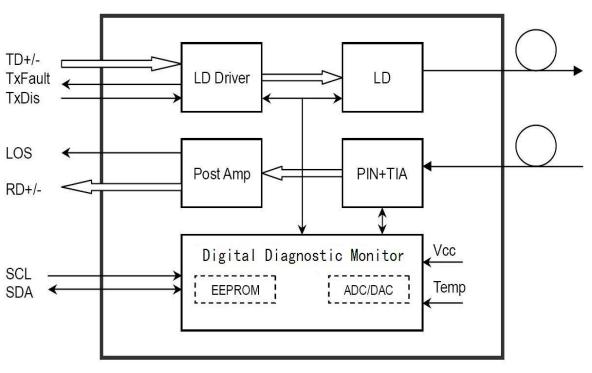
Module Block Diagram
Features
Applications
Standards
Recommended Operating Environment
Parameter |
Symbol |
Min. |
Typical |
Max. |
Unit |
|
Power Supply Voltage |
VCC |
3.13 |
3.3 |
3.46 |
V |
|
Power Supply Current |
ICC |
|
|
300 |
mA |
|
Operating Case Temperature |
Commercial |
TC |
-5 |
|
+70 |
。C |
Data Rate |
|
|
10.3125 |
|
Gbps |
|
Electrical Characteristics
Parameter |
Symbol |
Min. |
Typical |
Max. |
Unit |
Note |
Transmitter Section |
|
|||||
Input Differential Impedance |
Rin |
90 |
100 |
110 |
Ω |
|
Differential Data Input Swing |
Vin PP |
180 |
|
700 |
mV |
1 |
Transmit Disable Voltage |
VD |
Vcc – 1.3 |
|
Vcc |
V |
|
Transmit Enable Voltage |
VEN |
Vee |
|
Vee+ 0.8 |
V |
|
Receiver Section |
|
|||||
Differential Data Output Swing |
Vout PP |
300 |
|
850 |
mV |
|
LOS Fault |
Vlos fault |
Vcc – 0.5 |
|
Vcc_host |
V |
2 |
LOS Normal |
Vlos norm |
Vee |
|
Vee+0.5 |
V |
2 |
Optical Parameters
Parameter |
Symbol |
Min. |
Typical |
Max. |
Unit |
Note |
Transmitter Section | ||||||
Centre Wavelength |
λc |
840 |
850 |
860 |
nm |
|
Spectral Width (RMS) |
σ |
|
|
0.45 |
nm |
|
Average Optical Power (avg.) |
Pout |
-6.5 |
|
-1 |
dBm |
1 |
Laser Off Power |
Poff |
- |
- |
-30 |
dBm |
|
Extinction Ratio |
ER |
3.0 |
5.0 |
- |
dB |
2 |
Relative Intensity Noise |
RIN |
- |
- |
-128 |
dB/Hz |
|
Optical Rise/Fall Time |
tr / tf |
|
- |
50 |
ps |
3 |
Optical Return Loss Tolerance |
|
- |
- |
12 |
dB |
|
Output Optical Eye |
Compliant with IEEE802.3ae eye masks when filtered |
2 |
||||
Receiver Section |
|
|||||
Receiver Center Wavelength |
λc |
840 |
|
860 |
nm |
|
Receiver Sensitivity |
Sen |
- |
- |
-11.1 |
dBm |
4 |
Stressed Receiver Sensitivity(OMA) |
Sens |
- |
- |
-7.5 |
dBm |
|
Los Assert |
LOSA |
-30 |
- |
- |
dBm |
|
Los Dessert |
LOSD |
- |
- |
-13 |
dBm |
|
Los Hysteresis |
LOSH |
0.5 |
- |
5 |
dB |
|
Overload |
Pin-max |
- |
- |
-1 |
dBm |
4 |
Receiver Reflectance |
|
- |
- |
-12 |
dB |
|
Receiver power (damage) |
|
- |
- |
1.5 |
dBm |
|
Notes:
1. The optical power is launched into 50/125µm MMF.
2. Measured with a PRBS 231 - 1 test pattern @10.3125Gbps.
3. Unfiltered, 20-80%. Measured with a PRBS 231 - 1 test pattern @10.3125Gbps.
4. Measured with a PRBS 231 - 1 test pattern @10.3125Gbps, ER=4dB, BER <10-12 .
Pin Definitions
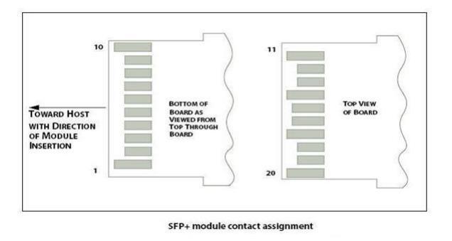
Pin Descriptions
Pin |
Signal Name |
Description |
Plug Seq. |
Notes |
1 |
VeeT |
Module Transmitter Ground |
1 |
1 |
2 |
TX FAULT |
Module Transmitter Fault |
3 |
|
3 |
TX Disable |
Transmitter Disable; Turns off transmitter laser output |
3 |
|
4 |
SDA |
2-Wire Serial Interface Data Line |
3 |
2 |
5 |
SCL |
2-Wire Serial Interface Clock |
3 |
2 |
6 |
Mod_ABS |
Module Definition, Grounded in the module |
3 |
|
7 |
RS0 |
Receiver Rate Select (not used) |
3 |
|
8 |
LOS |
Receiver Loss of Signal Indication Active LOW |
3 |
|
9 |
RS1 |
Transmitter Rate Select (not used) |
3 |
|
10 |
VeeR |
Module Receiver Ground |
1 |
1 |
11 |
VeeR |
Module Receiver Ground |
1 |
1 |
12 |
RD- |
Receiver Inverted Data Output |
3 |
|
13 |
RD+ |
Receiver Non-Inverted Data Output |
3 |
|
14 |
VeeR |
Module Receiver Ground |
1 |
1 |
15 |
VccR |
Module Receiver 3.3 V Supply |
2 |
|
16 |
VccT |
Module Transmitter 3.3 V Supply |
2 |
|
17 |
VeeT |
Module Transmitter Ground |
1 |
1 |
18 |
TD+ |
Transmitter Non-Inverted Data Input |
3 |
|
19 |
TD- |
Transmitter Inverted Data Input |
3 |
|
20 |
VeeT |
Module Transmitter Ground |
1 |
1 |
Notes:
Plug Seq.: Pin engagement sequence during hot plugging.
1. Module ground pins GND are isolated from the module case.
2. Shall be pulled up with 4.7K-10Kohms to a voltage between 3.15V and 3.45V on the host board.
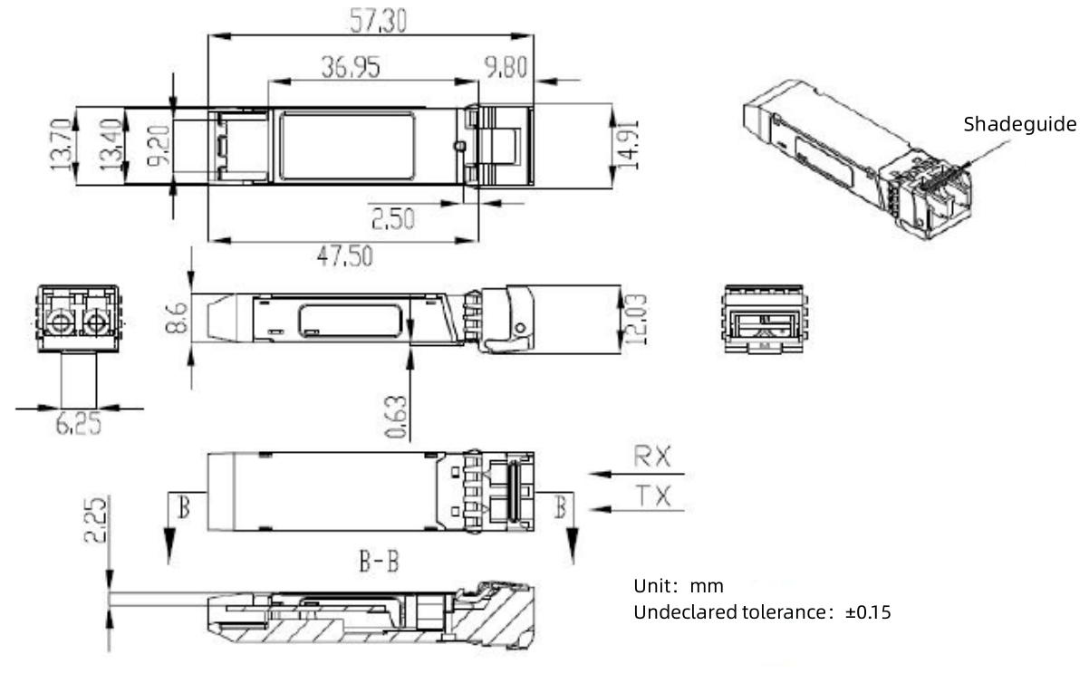
Mechanical Dimensions